This article comprehensively explains scientific injection molding theory from 6 aspects.
Here we go!
Injection molding theory of viscosity of injection molding

Newtonian fluid is a fluid whose viscosity is not affected by the shear rate applied to it. When the shear changes, the viscosity remains constant.
Non-Newtonian fluid is a fluid whose viscosity varies with the shear rate. When the shear changes, the viscosity does not remain constant.
Rheology is the study of fluid flow in non-Newtonian fluids.
All plastics are non-Newtonian fluids.
This means that their viscosity will not remain constant over a range of shear rates.
In a strict sense, the rheological behavior of plastics is a combination of non-Newtonian and Newtonian mechanics. At lower shear rates, plastics are non-Newtonian, but as the shear rate increases, they tend to exhibit Newtonian behavior.
This is because as the shear rate increases, the polymer molecules begin to separate from each other and begin to align in the flow direction. The reference is as follows.

During the injection molding process, the material is subjected to a large amount of shear during the cavity-filling phase.
The shear rate is proportional to the injection speed. If the shear rate is in the non-Newtonian region of the curve, then a small change in the shear rate will cause a large displacement in viscosity.
This will cause inconsistent mold filling and thus affect mass-produced products. Therefore, it is important to find the Newtonian region of the curve and set the injection rate (and, therefore, the shear rate) within this region.
Viscosity profiles can be obtained for any mold using an injection molding machine. The shear rate has a much greater effect on the viscosity than the temperature. Therefore, as long as the actual melt temperature is within the recommended range, a similar viscosity profile will be obtained during the molding process.
Injection Molding Theory of Cavity Equilibrium
When plastic enters the cavity through the runner, the melt has a certain temperature, pressure, and velocity. All three variables are time-dependent, meaning that each variable’s value will change over a short period of time until the end of filling.
For example, the melt temperature decreases with time. If a melt temperature of 280°C is injected, one second later, the melt temperature is below 280°C. The final size and quality of each finished injection mold depend partly on temperature, pressure, and speed.
Consider a one-cavity mold.
The melt temperature at the end of filling is 450 degrees Fahrenheit, the plastic pressure is 8,000 psi, and the plastic enters the cavity at a rate of 4.5 inches per minute. If the temperature drops to 400 degrees Fahrenheit, the part will shrink less, producing a part that is now larger than the last. Similarly, if the end of fill pressure and velocity change, the part’s size and/or end will change.
Now consider a two-cavity mold where each cavity has the same cavity size.
Based on the discussion above, if the two cavities are not filled with similar filling conditions, we know that the two parts produced from each cavity will be different.
This is the reason why cavity balance testing is needed.
Injection Molding Theory of Pressure Retention and Process Windows
Plastic injection into a cavity can be divided into two main stages.
The first stage is the injection stage. During the injection stage, the mold cavity is filled with molten plastic.
The second stage is the replenishment stage. The make-up shrinkage stage follows the injection stage. The shrinkage pressure must fill the mold cavity with plastic equivalent to the volume shrinkage that occurs during the cooling of the plastic as it hits the cold walls of the mold.
In most cases, the make-up shrinkage and holding phases are not distinguished and are collectively referred to as the holding pressure phase.
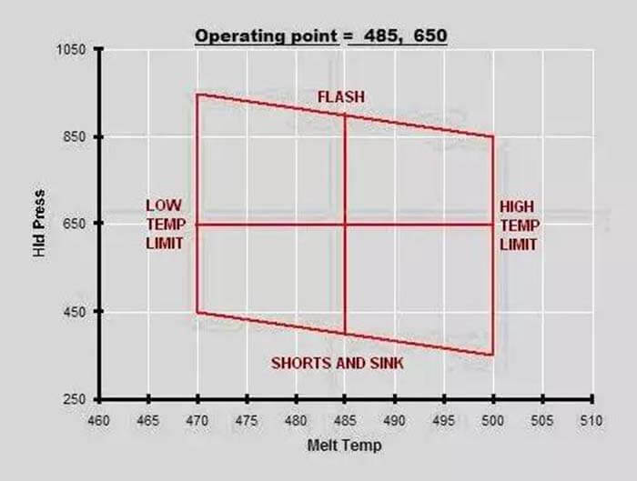
The ideal holding pressure is determined by evaluating the process window of the mold.
The process window is also referred to as the molding area map. This is the area where the good part is molded. The larger the window, the greater the range of molding fluctuations allowed. As follows.

The process is set in the center of this window so that any variation within the window will produce an acceptable part.
Injection Molding Theory of Gate Closure
Plastic enters the cavity through the gate. As long as the gate does not freeze, the plastic can enter or leave the cavity.
Therefore, holding pressure must be applied until the gate is frozen.
A very simple test is performed to determine the holding time.
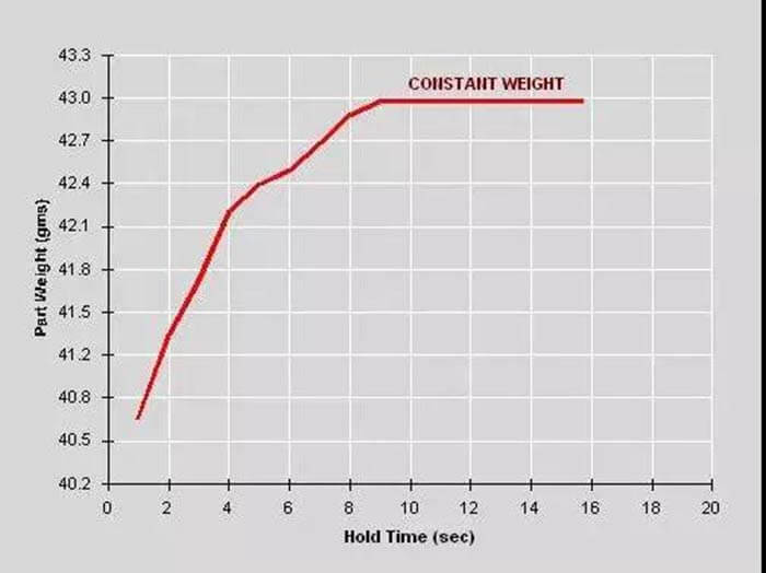
Weighing the sample for different holding times, more and more plastic enters the cavity adding weight as the holding time increases. However, once the gate freezes, the plastic cannot enter the cavity and the part weight remains the same. This is called gate freeze time or gate closure time. See the following figure.

In the above diagram, the part weight stays the same after 9 seconds. The hold time is set to one second higher than the gate seal time to ensure that the gate is frozen during each pour. In the case of the graph below, the time is set to 10 seconds. This will ensure consistency and any small variations will be compensated for.
Injection Molding Theory of Injection Molding Cooling
Once the plastic touches the walls of the mold, it begins to cool.
The mold remains closed until the cooling time is complete. Then the mold opens and the part is ejected. Before the mold can be opened, the part must reach an acceptable ejection temperature for the plastic.
If the part is ejected before it reaches an acceptable ejection temperature, the part is too soft and will deform during the ejection process. And excessive cooling time is just a waste of machine time and profit.
Determining the proper cooling time is complicated.
In parts with thick sections, it is difficult to measure the internal temperature in the center of the thickest part. In some parts of the mold, it is difficult to get sufficient cooling.
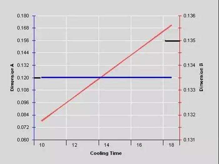
Variations in cooling time can also affect shrinkage.

In the figure above, size A (blue) is not affected by the cooing time range test. However, size B (red) varies with cooling time. The target value for size B is 0.135. So we can set the cooling time at about 17 seconds.
Besides the 6 Aspects of Scientific Injection Molding Theory article, you may also be interested in the below.
