Description
What are the Oil-Free SCY Slide Units For Loose Core?
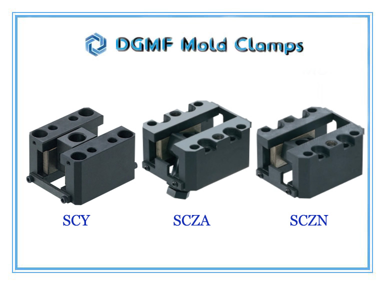
The SCY Slide Units DGMF-MOLD-CLAMPS-EM-SCY is an oil-free slide unit with 2 specs JIS standard SCY model ejection mechanism supplied by DGMF Mold Clamps Co., Ltd. for the injection mold loose core application.
DGMF Oil-Free Slide Units For Loose Core SCY Series Features
Enables the inclined pin to slide smoothly when pushing out a loose core (including undercut) at an angle.
The inclined pin guide slides within the size range, and the automatic center adjustment function reduces wear and scoring on the guide and slide plates.
etc.
DGMF Mold Clamps Co., Ltd supplies mold clamps, injection mold components, machine tools, hopper dryers, and accessories. We are dedicated to offering cost-effective standard and non-standard secondary ejection mechanism ejectors for your choice.
Contact us for more details on the SCY slide units.
DGMF Oil-Free Slide Units For Loose Core SCY Series Specifications
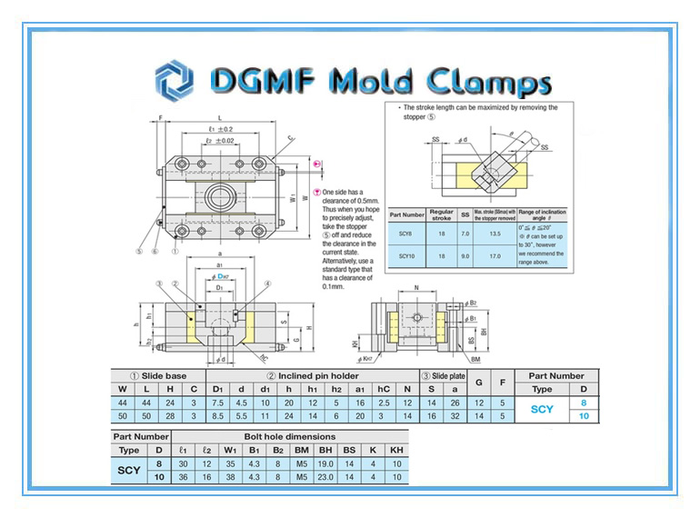
| SKU | ①Slide Base | ②Inclinde Pin Holder | ③Slide Plate | G | F | |||||||||||||
| Type | D | W | L | H | C | D1 | d | d1 | h | h1 | h2 | a1 | Hc | N | S | a | ||
| DGMF-MOLD-CLAMPS-EM-SCY-8 | 8 | 44 | 44 | 24 | 3 | 7.5 | 4.5 | 10 | 20 | 12 | 5 | 16 | 2.5 | 12 | 14 | 26 | 12 | 5 |
| DGMF-MOLD-CLAMPS-EM-SCY-10 | 10 | 50 | 50 | 28 | 3 | 8.5 | 5.5 | 11 | 24 | 14 | 6 | 20 | 3 | 14 | 16 | 32 | 14 | 5 |
| SKU | Mounting Bolt Hole Dimensions | ||||||||||
| Type | D | ℓ1 | ℓ2 | W1 | B1 | B2 | BM | BH | BS | K | KH |
| DGMF-MOLD-CLAMPS-EM-SCY-8 | 8 | 30 | 12 | 35 | 4.3 | 8 | M5 | 19 | 14 | 4 | 10 |
| DGMF-MOLD-CLAMPS-EM-SCY-10 | 10 | 36 | 16 | 38 | 4.3 | 8 | M5 | 23 | 14 | 4 | 10 |
DGMF Oil-Free Slide Units For Loose Core SCY Series Drawing
DGMF Oil-Free Slide Units For Loose Core SCY Series Installation
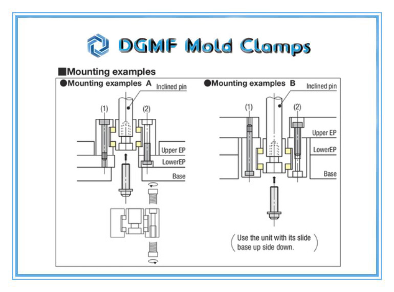
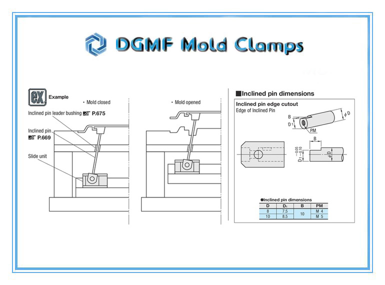
1. Refer to the above table for the dimensions of the inclined pin’s edge cutout and screw size (PM). The counterbore on the inclined pin holder is made in a size that accommodates a socket head cap screw with a spring washer.
2. The unit can be mounted on an ejector plate in two ways:
(1) Screwing into the ejector plate, or (2) Screwing into the unit.
For (2) use a socket head cap screw that corresponds to BM in the Bolt hole dimensions table.
For (1) select a rank below the corresponding BM (i.e., M6 screw when BM is M8).
3. Before mounting, apply grease to the unit to protect it from wear during the initial running-in.
4. If the stroke is long, it is recommended that you use a bushing that supports the inclined pin.
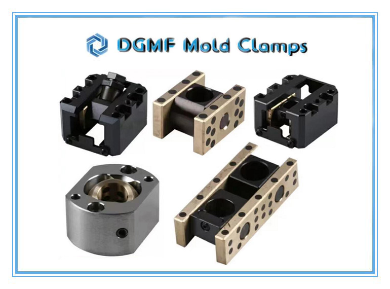
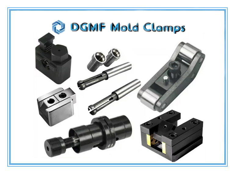
Similar secondary demoulding mechanism, and secondary ejection mechanism:
