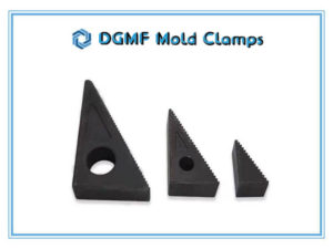
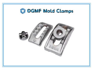
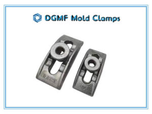
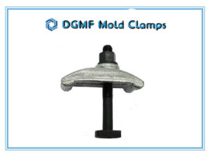
DGMF Mold Clamps Co., Ltd is a leading mould clamp manufacturer and mold clamp supplier in China.
For 10 Years, We Have Been Manufacturing Mold Clamps
99% of customers are very to cooperate with Hualida Tools.
More than 98.5% customers praise our mold clamp products.
Over 95% of our customers return to choose our mold clamps and recommend us.
About DGMF Mold Clamps
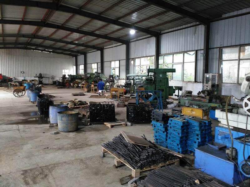
Mold Clamps Supplier
DGMF Mold Clamps Co., Ltd is a leading mold clamps supplier.
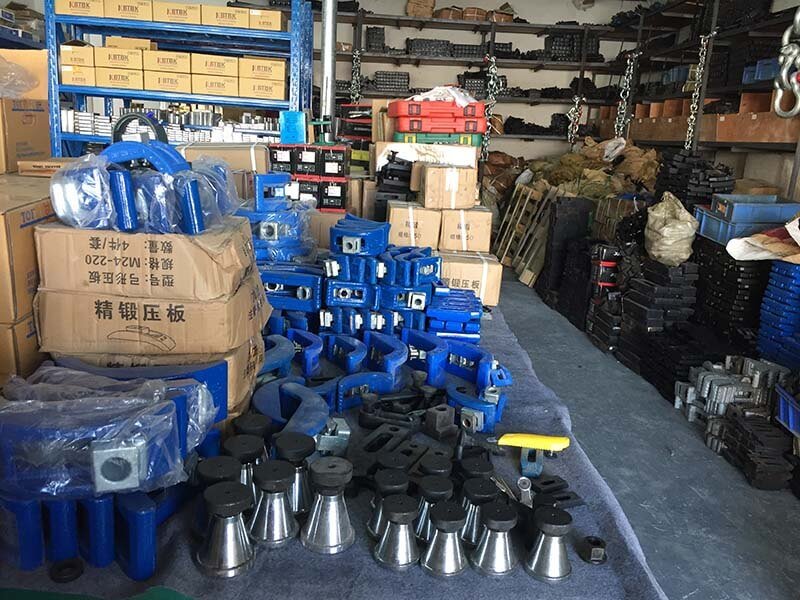
Mould Clamps Manufacturer
DGMF Mold Clamps Co., Ltd is a professional mould clamps manufacturer.
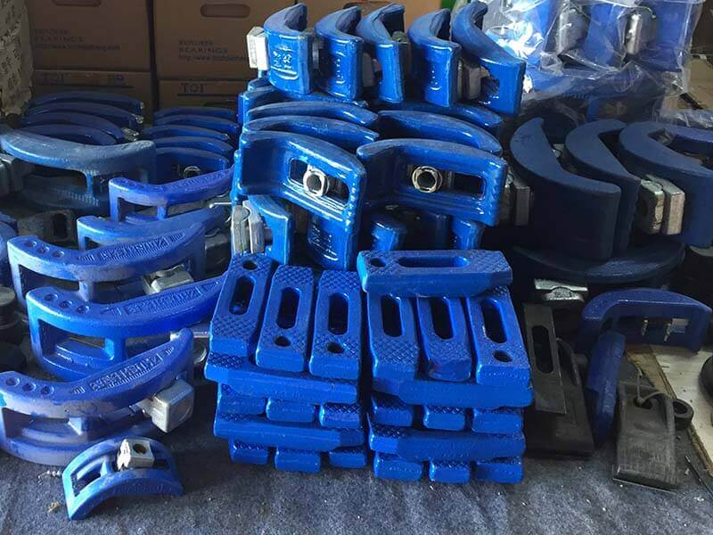
Large Storage
DGMF Mold Clamps Co., Ltd has a large storage of mold clamps, bolts, nuts, and washers.
who we are
Mould Clamp Manufacturer
Wide Selection
DGMF Mold Clamps manufacturer carries a wide range selection of mold clamps catering to different applications and professional requirements.
Fast Delivery
All mold clamps are available in stock and supported by a fast delivery service. This is to not cause delay to existing projects of the clients.
Durable Materials
DGMF Mold Clamps Co., Ltd uses high-quality and durable materials in producing every single mold clamp component. This is to provide you with powerful mold clamps that will live on the job site.
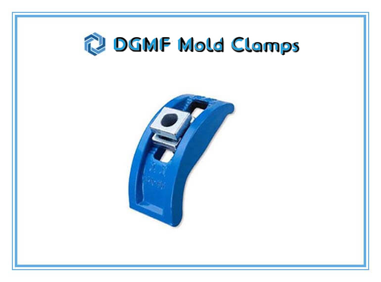
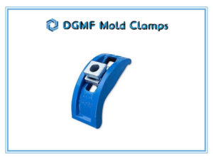
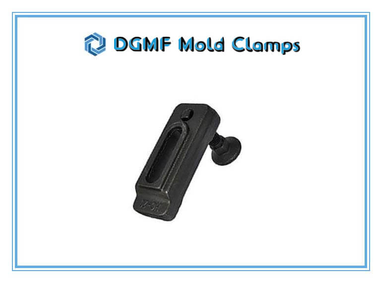
Quick Change Mold Clamp
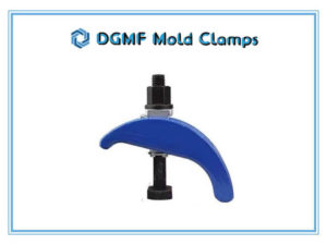
Quick-change mold clamp is typically used for injection molding
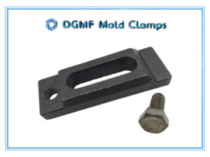
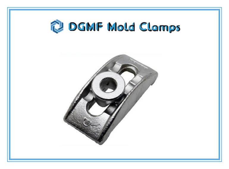
Forged Mold Clamp
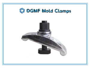
Forged Mold Clamp is typically used for injection molding & die-stamping.
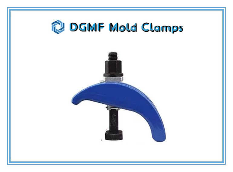
Clamp for mold
The forged clamp for mold clamping is typically used for CNC milling & die-stamping machines.
Mould Clamp Manufacturer & Mold Clamp Supplier
DGMF Mold Clamps Co., Ltd is a professional mould clamp manufacturer and mold clamp supplier in China.
DGMF Mold Clamps Co., Ltd supplies all the mold clamps specifications, including M10, M12, M14, M16, M18, M20, M22, M24, M30, M36, etc.
The mold clamp types include closed-end, open-end, strapped, stepped, quick-change, forged, hardened, and high-quality precision mold clamps.
Featured mold clamps
The T Bolt Mold Clamp Assembly Set includes the following:
1 PC Quick-change Mold Clamp
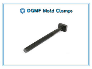
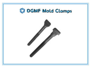
1 PC T Bolt
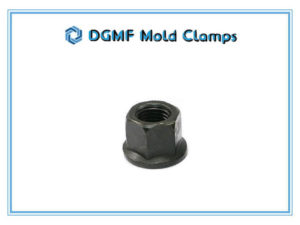
1 PC Flange Nut
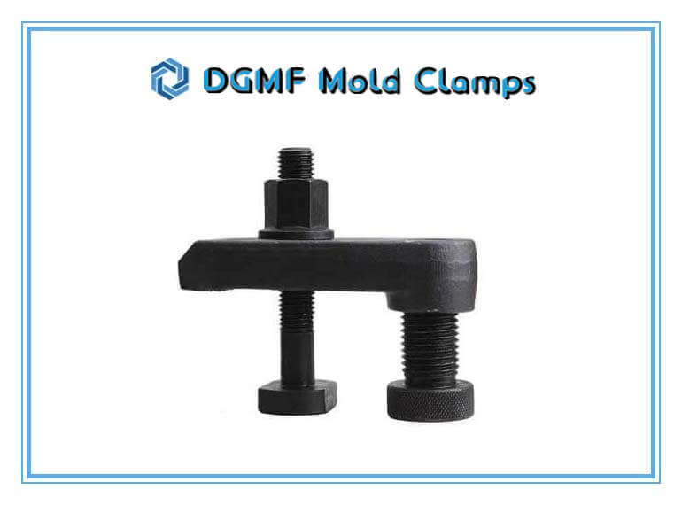
The Forged Mold Clamp For Injection Molding Assembly Set includes the following:
1 PC Forged Injection Mold Clamp
1 PC T Bolt
1 PC Flange Nut
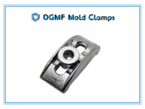
The universal mold clamp Assembly Set includes the following:
1 PC Universal Mold Clamp
1 PC T Bolt
1PC Flange Nut
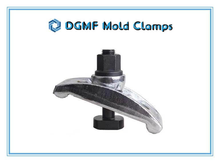
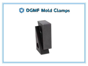
The universal mold clamp Assembly Set includes the following:
1 PC Step Block
1PC Strap Clamp
1 PC T Bolt
1PC Flange Nut
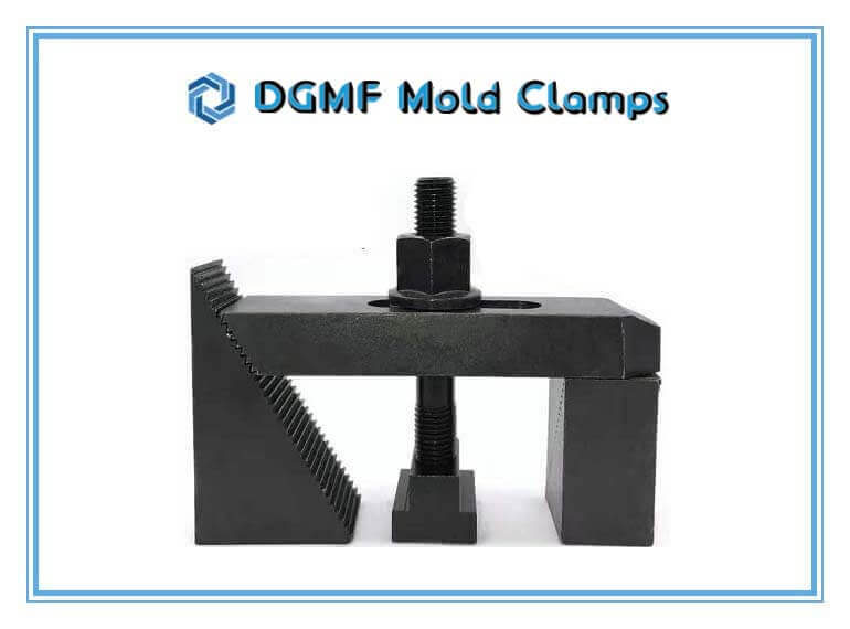
What Our customers say

I've worked with DGMF Mold Clamps for more than 5 years, their mold clamps are very durable.
Lizzie Thompson

I was introduced to DGMF Mold Clamps many years ago, and I buy mold clamps from then on.
Emma Velasquez
Advantages
Large Storage
- 4 big warehouse of mold clamps storages
- Full range of mold clamps styles and specifications available
Direct Manufacturer
- Factory direct mold clamp pricing
- Next day shipment
- Custom mold clamp service available
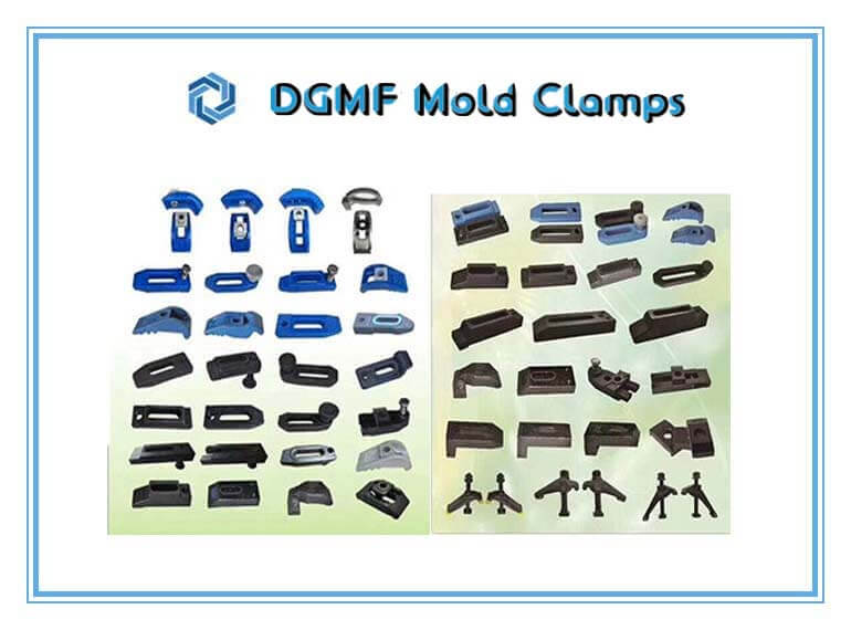
Pick the below mold clamp types that best fit your machines. All mold clamps are available in stock. If you cannot find the suitable one, contact us!
Mold Clamps For Injection Molding
Mold Clamps And Mounts
Quick Mold Clamps
Mold Clamps Injection Molding
Mold Clamp Assembly
Arching Mold Clamps
Mold Clamp Bolts
Quick Mold Change Clamps
Mold Clamp For Jewelry
Injection Mold Clamp Factor For Pp
Mold Clamp Injection Moulding
Mold Clamp Misumi
Mold Mounting Clamps
Plastic Mold Clamp Manufacturer
Machined Mold Clamps
Mold Clamp Washer
Injection Mold Clamps
Injection Mold Toe Clamps
Clamp Mold
Clamp Lock Mold
Mold Toe Clamps
Metric Mold Clamps
Mold Clamp M16
Mold Handle Clamp
Forged Mold Clamps
Mold Clamp Injection Molding
Magnetic Mold Clamp
Plastic Mold Clamp
Rubber Mold Clamp
Zhushi Mold Clamps
Zhushi Mould Clamps
Plastic Injection Mold Clamps
Mold Clamping Unit
A Mold Clamp
Mold Cutting Clamp
Injection Mold Clamp
Quick Mold Clamp
Mold Clamps Adjustable
Mold Clamps Holding Weight
Mold Clamps For Steel Molding
Mold Clamps For Injection Molding Crab
Mold Clamps For Holding
Molds To Platens
Mold Clamps Near Me
Mold Clamps Supplier Near Me
Mold Clamps Manufacturer Near Me
Mold Clamps Store Near Me
Matex Mold Clamps
Manual Mold Clamps
Magnetic Mold Clamps
Dme Machine Mold Clamps
Injection Molding Mold Clamps
Punch Mold Clamps
Ppe Mold Clamps
Mold Clamps Dme
Tapped Clamp Strap
Clamp Strap Assemblies
Adjustable Strap Clamp
Plastic Injection Mold Clamps
Parting Line Mold Clamps
Mold Clamp Rectangular Washers
7/16 T Slot Clamping Kit
5 8 T Slot Clamp Set
58 Pc Steel Clamping Kit
58pc Deluxe Steel Clamping Kit
Mold Smart Clamp
Forged Tapped End Mold Clamp
Stepped Strap Clamps
Strap Clamps
Tapped End Mold Clamp
U-clamp For Injection Molding
U-shaped Mold Clamp
Machined Mold Clamps
Machined Closed Toe Clamp
Machined Open Toe Clamp
Injection Molding Clamps
Mold Clamps T Bolt
Setup Mold Clamps
Setup Clamps
Low-profile Clamps
Low-profile Setup Clamps
Step Setup Clamps
Step Setup Mold Clamps
Setup Clamp Supports
Side Clamps
Milling Machine Clamps
Milling Machine Mold Clamps
Milling Machine Clamp Kits
Machinist Clamp Kits
Step Block Mold Clamp Kit
Step Block Clamp Kit
Step Blocks
Single Toe Clamp
Plain Clamps
Tapped End U-clamp
Stepped End Clamps
Serrated End Clamp
Step Clamps
Forged Plain Clamps
Forged Tapped Plain Clamps
Forged U Clamps
Forged Finger-tip Clamps
Forged Gooseneck Clamps
Heavy-Duty Mold Clamps
Clamp For Fixing Mold
Mold Clamp Forged
Forged Mould Clamp
Milling Clamps
Forged Tapped Plain Mold Clamp
Forged Quick Mold Clamp
Forged Quick Arching Clamp
Forged Arching Clamp
Die Clamps
Standard Die Clamp
Open Toe Die Clamp
Forged U Clamp
Forged Gooseneck Clamp
Quick Change Arching Mold Clamps
Mold Press Clamp
Mold Clamp With Adjustable
Support Bolt
Strap Mold Clamp
Strap Mould Clamp
T-slotted Mold Clamp
Injection Molding Machine Clamps
Press Tool Clamp
Mold Clamp With T Slot Bolt
Toyo Mold Clamps
Small Mold Clamps
Ejection Mold Clamps
Injection Mold Clamps For Sale
Closed Slot Mold Clamps
Closed Slot-style Mold Clamps
Open Slot Mold Clamps
Open Slot Style Mold Clamps
Easy Mold Clamps
Easy Clamps
Open Toe Mold Clamps
Open Toe Style Mold Clamps
Closed Toe Mold Clamps
Closed Toe Style Mold Clamps
Clamping Elements
Press Strap Clamps
U-type Mold Clamps
T-slot Clamps
Strap Clamps
C Washer
Tapped End Clamps
Tapped End Mold Clamps
Tapped End Mould Clamps
For T Slot Machine Clamps
For T Slotted Machine Clamps
Quick-change Mold Clamps
High-speed Mold Clamps
Quick Change Mould Clamps
High-Speed Mould Clamps
Quick Mold Clamps
Quick Mould Clamps
High-Speed Quick-change
Mold Clamps
Heavy-duty Quick-change
Mold Clamps
Din 6314 Steel Plain Clamps
Din 6314 Clamps
Plain Clamp Din 6314
Simple Clamp Din 6314
Clamp Straps Din 6314
Din 6314 Straight Clamp
Din 6314 Mechanical Clamping
Clamps Din 6314
Clamp Flat Din 6314
Plain Clamps Din 6314
Din 6314 Plain Clamps
Closed Toe Plain Clamps
Molding Clamps
Clamp Mold
U Mold Clamps For Injection Molding
Step Clamp Set
Mold Die Clamps For Injection Molding
58pc Clamping Kit
T Slot Quick Clamp
T Slot Toe Clamps
T Slot Nuts
T-slot Clamping
Tapped T-nuts
Flange Nuts
Hex Nuts
T Slot Nuts
Clamping Stud Hex Spanner Bolts
Swivel Levelling Bolt
Rectangle Washer For Mold Clamp
Mold Clamp Washers
No-twist Rectangular Mold Washer
No Turn Washer
Extension Nuts
Hold Clamps
BUY MOLD CLAMPS
Contact DGMF Mold Clamps Company NOW!
-
Quick Change Mold Clamp
Read more -
DGMF Forged Mold Clamps Closed-end Style
Read more -
Forged Uni Clamp for Mold
Read more -
Step Block Mold Clamps
Read more -
Heavy-duty Step Blocks
Read more -
Forged Smart Clamp for mold clamping
Read more -
Hardened Universal Mould Clamp
Read more -
Forged Uni Mold Clamp Set
Read more -
Heavy-duty Universal Mold Clamp Set
Read more -
High-quality T Bolt Mold Clamp Set
Read more -
Heavy-duty T Bolt
Read more -
Heavy-duty Mold Clamping Stud With A Spanner
Read more -
Heavy-duty Flange Nut
Read more -
High Strength T Slot Bolts
Read more -
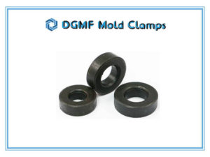
Heavy-duty Mold Clamp Washers
Read more -
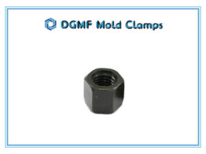
ASTM A194 DGMF Heavy Hex Nut
Read more
Best Mold Clamp Price Quote Now
Have your questions about DGMF Mold Clamps Co., Ltd? Can’t find the right mold clamps you need? Let our sales team help you with that.
Newest Products
-
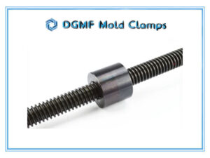
DGMF Metric Trapezoidal Threaded Rods DIN 976 1M
Read more -
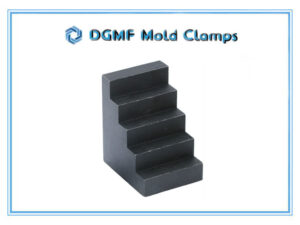
DGMF Step Block Clamps
Read more -
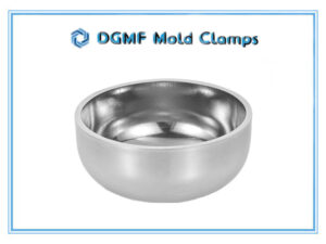
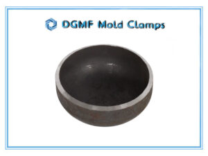
DGMF 304 & 316 Stainless Steel Elliptical Heads
Read more -
DGMF 304/316 SS Semi-ellipsoidal Heads
Read more -
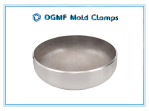
DGMF 2:1 Elliptical Head Carbon Steel
Read more -
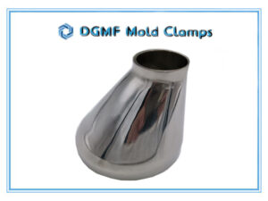
DGMF 304 & 316 Stainless Steel Eccentric Reducers
Read more -
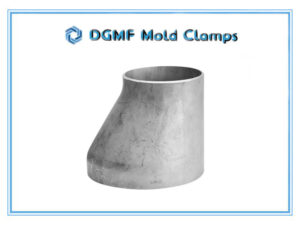
DGMF 304 SS Eccentric Reducers Unpolished
Read more -
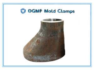
DGMF Carbon Steel Eccentric Reducers Ф27-630
Read more -
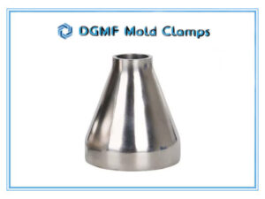
DGMF 304 & 316 Stainless Steel Concentric Reducers
Read more -
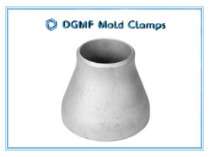
DGMF 304 Stainless Reducers Unpolished
Read more -
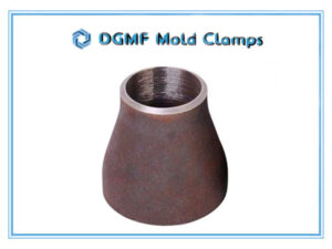
DGMF Carbon Steel Concentric Reducers Ф25-325
Read more -
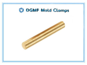
DGMF Brass Full-thread Studs
Read more -
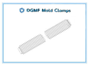
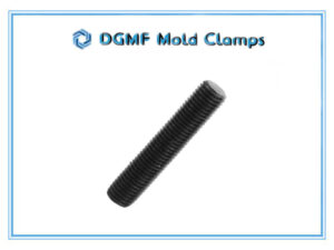
DGMF Fully Threaded Rods 1-Meter Long
Read more -
DGMF Class 12.9 Stud Full-Thread
Read more -
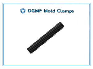
DGMF Class 8.8 Stud Bolt Fully Threaded
Read more -
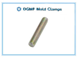
DGMF Color Zinc Full Thread Stud Bolts
Read more
Services

Mold Clamps Supply
DGMF Mold Clamps company provides a wide range of mould clamps for injection moulding, CNC machining, drilling, stamping, etc.
Tools Supply
DGMF Mold Clamps company provides thousands of tools you may need in all industries such as machine tools, injection molding tool companents, element tools, etc.
DGMF Mold Clamps Company's New Articles
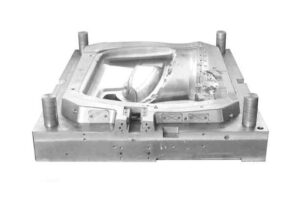
5 Special Precision Injection Moulding Design Guides
After reading this 5 Special Precision Injection Moulding Design Guides article, you will know 5 important points of precision injection moulding design guidelines. Injection moulding
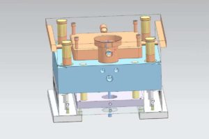
12 Major Injection Moulding Processes Explained
This 12 Major Injection Moulding Processes Explained article talks about what is injection moulding and the 8 kinds of injection moulding processes processing, advantages, disadvantages,
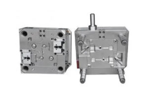
What Are The Effects of Mold Temperature In Injection Molding?
This article discusses the effect of mold temperature in injection molding in 4 areas: What are the factors that affect the cooling of the injection
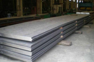
What is 45# Steel Material?
What is 45# Steel? 45# steel is generally referred to as 45-grade steel, a high-quality carbon structural steel, characterized by higher strength and resistance to
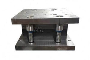
Stamping Die Design Guidelines, 75 Taboos And Rules
This article describes the Stamping Die Design Guidelines, the taboos of the three main stamping die design processes, namely blanking, bending and drawing, and the
Mechanical Design Steps and 525 Taboos
What is mechanical design? Mechanical design is the design of parts, components, products, or systems of a mechanical nature. For example, mechanical design includes the

5 Factors Affect the Shrinkage of Thermoplastic Molding
What are the factors that affect the shrinkage of thermoplastic molding? The following are 5 factors that affect the shrinkage of thermoplastic molding and the
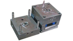
17 Injection Molding Problems And Solutions
After reading, you will know 17 injection molding problems and solutions. Injection molding problems and Solutions 1. Scrap jumping hole The punch length is not

